


- Guaranteed Secure Payments on Every Order
- Refund if your item is not delivered or as described
- Buyer Protection after order confirmation
- Place of Origin: TAIAN
- Brand Name: HONGJIAN
- Model Number: HZS90
- Weight: 62.600 kg
No. | Name | Technical data and specification | Remarks |
1 | The mixing system | 1. Model: YJS1500 2. Type: Twin-horizontal forced type 3. Charging volume: 2400 L 4. Discharging volume: 1500 L 5. Discharging height: 3.8m 6. Max aggregate diameter: 80/60mm (cobblestone/ broken stone) 7. Reducer power: 30KW, 2 units 8. The mixing blade lining board: high chrome wear- resistance material.
System instruction: 1. The mixer is reasonably designed with short mixing time, low consumption, low noise and long service life. 2. The mixing blade and lining board use wear-resistance material. They have long service life and are easy to dismantle and replace. 3. Driving device and shaft end sealing device imitate technology of SICOMA, ITALY 4. The discharging gate is controlled by hydraulic oil pump, having three stick points, opening brake manually, without noise | According to customer’s demand, SICOMA MAO2250/1500 mixer is optional.
|
2 | Electric control system | Electric system is composed of host computer, display, printer, communication cable, weighing instrument and so on. 1. The operation is integrated with management .It is easy and convenient to operate. 2. The batching system is controlled by microcomputer. 3. The operating data of the mixing plant can be saved for more than ten years for the convenience of setting management. 4. The formula which can reach more then dozens can express by the figures for the convenience of distinguishing. 5. Under the condition departing from the automatic control .The manual operating system can finish the control of the mixing plant such as batching, mixing discharging and so on. 6. The heavy-current part of the system is separated from the weak-current part, so it enhances the ability of anti-jamming. Easy to maintain. 7. Equipped with monitoring system.
System instruction: The system has the features of advanced performance, high reliability and beautiful exterior. Console is designed by adopting man-machine engineering principle. | |
3 | The hoisting system | The hoisting system adopt high flange belt conveyor. 1. Electric drum: YZ1-18.5-2.0-80×63-S 2. Power: 18.5Kw 3. High flange specification: B=800 4. Belt speed: 2.0m/s 5. Conveying ability: 260m3/h
System instruction: Adopting high flange belt conveyer can save space. The well designed cover of the conveyor can fit the all-weather working .The temporary storage hopper shorten the batching time can improve the productivity . | Standard collocation is hoisting system Ⅰ that is high flange conveyer; users can choose hoisting system Ⅱ that is loop flat belt conveyer.
|
4 | Aggregate temporary storage hopper | 1. Volume: 2.8m3 2. Vibrator: MVE100/3, 0.09kW 3. Cylinder: HCDA2C80-200Y-YV51A-4D
System instruction: Temporary storage hopper can store a tank of aggregate, so it saves time and improves the productivity. | |
5 | Aggregate batching and weighing system | Aggregate weighing system is composed of aggregate bin, frame ,aggregate conveyer, sensors and so on. 1. Aggregate bin a. Volume: 15m3×4 b. Discharging gate, 8 units c. Cylinder:HCDA2C80-300Y-YV51B-4D, 8 units 2. The weighing hopper a. Volume: 1400L×4 b. Measuring manner: measuring alone c. Sensor: 1000kg×12 d)Cylinder:HCDA2T100-300Y-YV51B-4D, 4 units e)Measuring precision: ±2% 3. Belt conveyer a. Belt specification: 800mm b. Belt speed: 1.25 m/s 4. Electric drum a. Model: YZ7.5-1.25-80*50 b. Power: 7.5kw System instruction: The aggregate hopper adopts mechanical loader or charging belt conveyer for the charging .The aggregate bin has four hoppers with each volume of 15 m3.Each storage hopper has two discharging gate to realize the rough weighing and fine weighing .There are four aggregate measuring hoppers ,every weighing hopper is hung to storage bin bracket by three sensors .The signal sent out from the sensors are sent to microcomputer in control room after being dealt ,the signal display by secondary instrument changing into the weight value .The belt conveyer installed under the four weighing hoppers can deliver the well-batched aggregate to the temporary storage hopper of the top ,waiting for other material and are discharged into the mixer together. | |
6 | Cement weighing system | Cement weighing system is composed of cement weighing hopper, pneumatic butterfly valve, sensors and so on. Cement weighing system: 1. Volume: 950L 2. Weighing range: 0~1000 kg 3. Weighing precision: ±1% 4. Sensor: 500 kg×3 5. Pneumatic butterfly valve: Ф300
System instruction: The weighing hopper adopts full sealing device. The weighing hopper carries on the weighing by three sensors. The weighing hopper gate uses Italian pneumatic butterfly valve driving gate with easy opening and good sealing. |
the weighing hopper
the sensor |
7 | Fly ash weighing system | Fly ash weighing system is composed of fly ash weighing hopper, pneumatic butterfly valve, sensors and so on. Fly ash weighing hopper: 1. Volume: 600L 2. Weighing range: 0~650 kg 3. Weighing precision: ±1% 4. Sensor: 500 kg×3 5. Pneumatic butterfly valve: Ф250
System instruction: The weighing hopper adopts full sealing device. The weighing hopper carries on the weighing by three sensors. The weighing hopper gate uses Italian pneumatic butterfly valve driving gate with easy opening and good sealing. | |
8 | Powder weighing system | Powder weighing system is composed of powder weighing hopper, pneumatic butterfly valve, sensors and so on. Powder weighing hopper: 1. Volume: 600L 2. Weighing range: 0~650 kg 4. Weighing precision: ±1% 5. Sensor: 300 kg×3 6. Pneumatic butterfly valve: Ф250
System instruction: Powder weighing adopts all sealing device, weighing hopper weight through three sensors. Weighing hopper gate adopts typical pneumatic butterfly drive gate, open flexible and seal closely. | Powder weighing system is spare part, user can choose according to demand |
9 | Water weighing system | Water weighing system is composed of pool build by customer, water pump, water weighing hopper, pneumatic butterfly valve and so on. 1. Supply water pump model: QY50-18-4, 4kw 2. Discharging water pump type: ISG100-100(A), motor power: 4kw 3. Pneumatic butterfly valve type: DN100 4. Water scale volume: 500L 5. Sensor: 500kg×2 6. Weighing precision: ±1%
System instruction: Under the control of control system, Water pump pumps the water from the pool to the weighing hopper, when it is weighed to preinstalled value by sensors, The pump stop. When the discharging, the cylinder open, the water discharging pump starts to pump the water into the mixer. | |
10 | Liquid additive weighing system | Liquid additive weighing system, 2 sets Liquid additive weighing system is composed of additive storage box, additive weighing hopper, water pump, and sensors and so on. 1. Additive supplying pump model: GISGH25-125, 0.75kW 2. The three way pneumatic ball valve: Q615F-25 3. Additive scale: 45L 4. The additive storage box: 3m3 5. Weighing precision: ±1% 6. Sensor: 100kg×2 7. Pneumatic butterfly valve: DN50 8. Pneumatic ball valve: DN25
System instruction: Under the control of control system, the additive pump the additive from the additive box .when it is weighed to the preinstall value by the sensors. The three way pneumatic valve and charging butterfly valve close at the same time .When discharging, the pneumatic butterfly valve open to make the additive flow into the water measuring hopper and flow into the mixer together with water .Meanwhile the water pump continues working and take mixing effect by the other cycling additive of the three way ball valve to avoid the precipitation of additive. The water pump is controlled by the microcomputer. | |
11 | The Pneumatic control system | The pneumatic system is composed of air compressor, cylinder, electromagnetic valve, pneumatic component and so on. 1. Air compressor: LB150320, 11Kw 2. Electromagnetic valves 3. Cylinders 4. The gas source processing components
System instruction: The compressed air in the air compressor goes in the branch pipe after being purified by gas source processing components, pressure reduction and refueling. The pressure under normal working condition should be kept 0.5-0.7Mpa. | |
12 | Main frame bracket | It is composed of ladder, platform, and guardrail steel bracket and so on. | |
13 | Material-collecting | The collecting hopper is installed under the mixer. The well–mixed concrete slip into the concrete mover by collecting hopper | |
14 | The outer package | The main tower adopts sandwich plate decoration with good exterior. | |
15 | The dust collecting system | The dust collecting system is composed of dust collector, dust collecting pipe and so on. 1. The dust collector : YSCQ(Ⅰ) 2. Dust collecting pipe
System introduction: The main tower equips dust collecting device. The dust from main tower temporary hopper and powder is filtered in the sacks, and the vibrator will vibrate the sacks to make the dust drop every a certain time. | |
16 | Screw conveyer | Screw conveyer 1. Specification: Ф219×11000, 3 units 2. Capacity: 45t/h 3. Motor power: 11kw
System introduction 1. Cement screw conveyer adopts sealing device .The soft connection between the discharging gate and measuring hopper avoid the influence for the measuring accuracy. 2. The gate is universal fetlock which can regulate the angle wind age with good sealing. 3. The space between the screw blade and drum body is small with high conveying efficiency. | |
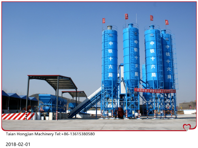
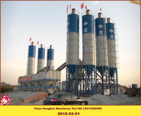
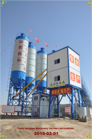
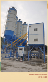
17 | Cement silo | Cement silo 1. Specification: 80t×3 2. Dust collector: 3 3. Impeding Level indicator: ULGA-240, 6 units
System introduction: The cement bin is equipped with high and low level indicator .The power is blown in from the top of the cement silo. The anti-spilling device is installed on the top which can lighten the loading pressure of the cement silo and prevent the pollution that the dust give the air .The arch-broken device installed at the conic section together with the pneumatic system and control system can carry on the automatic arch broken in time .You can also go on the manual arch broken. | |
18 | Control room | Control room: 1. Use color sandwich plate with function of heat-preservation and heat-insulation. 2. Air conditioner (changing with temperature) 3. Frame System instruction: The control room is commodious with good view. | |
19 | Total power | About 150kw |

- Place of Origin: TAIAN
- Brand Name: HONGJIAN
- Model Number: HZS90
- Weight: 62.600 kg
No. | Name | Technical data and specification | Remarks |
1 | The mixing system | 1. Model: YJS1500 2. Type: Twin-horizontal forced type 3. Charging volume: 2400 L 4. Discharging volume: 1500 L 5. Discharging height: 3.8m 6. Max aggregate diameter: 80/60mm (cobblestone/ broken stone) 7. Reducer power: 30KW, 2 units 8. The mixing blade lining board: high chrome wear- resistance material.
System instruction: 1. The mixer is reasonably designed with short mixing time, low consumption, low noise and long service life. 2. The mixing blade and lining board use wear-resistance material. They have long service life and are easy to dismantle and replace. 3. Driving device and shaft end sealing device imitate technology of SICOMA, ITALY 4. The discharging gate is controlled by hydraulic oil pump, having three stick points, opening brake manually, without noise | According to customer’s demand, SICOMA MAO2250/1500 mixer is optional.
|
2 | Electric control system | Electric system is composed of host computer, display, printer, communication cable, weighing instrument and so on. 1. The operation is integrated with management .It is easy and convenient to operate. 2. The batching system is controlled by microcomputer. 3. The operating data of the mixing plant can be saved for more than ten years for the convenience of setting management. 4. The formula which can reach more then dozens can express by the figures for the convenience of distinguishing. 5. Under the condition departing from the automatic control .The manual operating system can finish the control of the mixing plant such as batching, mixing discharging and so on. 6. The heavy-current part of the system is separated from the weak-current part, so it enhances the ability of anti-jamming. Easy to maintain. 7. Equipped with monitoring system.
System instruction: The system has the features of advanced performance, high reliability and beautiful exterior. Console is designed by adopting man-machine engineering principle. | |
3 | The hoisting system | The hoisting system adopt high flange belt conveyor. 1. Electric drum: YZ1-18.5-2.0-80×63-S 2. Power: 18.5Kw 3. High flange specification: B=800 4. Belt speed: 2.0m/s 5. Conveying ability: 260m3/h
System instruction: Adopting high flange belt conveyer can save space. The well designed cover of the conveyor can fit the all-weather working .The temporary storage hopper shorten the batching time can improve the productivity . | Standard collocation is hoisting system Ⅰ that is high flange conveyer; users can choose hoisting system Ⅱ that is loop flat belt conveyer.
|
4 | Aggregate temporary storage hopper | 1. Volume: 2.8m3 2. Vibrator: MVE100/3, 0.09kW 3. Cylinder: HCDA2C80-200Y-YV51A-4D
System instruction: Temporary storage hopper can store a tank of aggregate, so it saves time and improves the productivity. | |
5 | Aggregate batching and weighing system | Aggregate weighing system is composed of aggregate bin, frame ,aggregate conveyer, sensors and so on. 1. Aggregate bin a. Volume: 15m3×4 b. Discharging gate, 8 units c. Cylinder:HCDA2C80-300Y-YV51B-4D, 8 units 2. The weighing hopper a. Volume: 1400L×4 b. Measuring manner: measuring alone c. Sensor: 1000kg×12 d)Cylinder:HCDA2T100-300Y-YV51B-4D, 4 units e)Measuring precision: ±2% 3. Belt conveyer a. Belt specification: 800mm b. Belt speed: 1.25 m/s 4. Electric drum a. Model: YZ7.5-1.25-80*50 b. Power: 7.5kw System instruction: The aggregate hopper adopts mechanical loader or charging belt conveyer for the charging .The aggregate bin has four hoppers with each volume of 15 m3.Each storage hopper has two discharging gate to realize the rough weighing and fine weighing .There are four aggregate measuring hoppers ,every weighing hopper is hung to storage bin bracket by three sensors .The signal sent out from the sensors are sent to microcomputer in control room after being dealt ,the signal display by secondary instrument changing into the weight value .The belt conveyer installed under the four weighing hoppers can deliver the well-batched aggregate to the temporary storage hopper of the top ,waiting for other material and are discharged into the mixer together. | |
6 | Cement weighing system | Cement weighing system is composed of cement weighing hopper, pneumatic butterfly valve, sensors and so on. Cement weighing system: 1. Volume: 950L 2. Weighing range: 0~1000 kg 3. Weighing precision: ±1% 4. Sensor: 500 kg×3 5. Pneumatic butterfly valve: Ф300
System instruction: The weighing hopper adopts full sealing device. The weighing hopper carries on the weighing by three sensors. The weighing hopper gate uses Italian pneumatic butterfly valve driving gate with easy opening and good sealing. |
the weighing hopper
the sensor |
7 | Fly ash weighing system | Fly ash weighing system is composed of fly ash weighing hopper, pneumatic butterfly valve, sensors and so on. Fly ash weighing hopper: 1. Volume: 600L 2. Weighing range: 0~650 kg 3. Weighing precision: ±1% 4. Sensor: 500 kg×3 5. Pneumatic butterfly valve: Ф250
System instruction: The weighing hopper adopts full sealing device. The weighing hopper carries on the weighing by three sensors. The weighing hopper gate uses Italian pneumatic butterfly valve driving gate with easy opening and good sealing. | |
8 | Powder weighing system | Powder weighing system is composed of powder weighing hopper, pneumatic butterfly valve, sensors and so on. Powder weighing hopper: 1. Volume: 600L 2. Weighing range: 0~650 kg 4. Weighing precision: ±1% 5. Sensor: 300 kg×3 6. Pneumatic butterfly valve: Ф250
System instruction: Powder weighing adopts all sealing device, weighing hopper weight through three sensors. Weighing hopper gate adopts typical pneumatic butterfly drive gate, open flexible and seal closely. | Powder weighing system is spare part, user can choose according to demand |
9 | Water weighing system | Water weighing system is composed of pool build by customer, water pump, water weighing hopper, pneumatic butterfly valve and so on. 1. Supply water pump model: QY50-18-4, 4kw 2. Discharging water pump type: ISG100-100(A), motor power: 4kw 3. Pneumatic butterfly valve type: DN100 4. Water scale volume: 500L 5. Sensor: 500kg×2 6. Weighing precision: ±1%
System instruction: Under the control of control system, Water pump pumps the water from the pool to the weighing hopper, when it is weighed to preinstalled value by sensors, The pump stop. When the discharging, the cylinder open, the water discharging pump starts to pump the water into the mixer. | |
10 | Liquid additive weighing system | Liquid additive weighing system, 2 sets Liquid additive weighing system is composed of additive storage box, additive weighing hopper, water pump, and sensors and so on. 1. Additive supplying pump model: GISGH25-125, 0.75kW 2. The three way pneumatic ball valve: Q615F-25 3. Additive scale: 45L 4. The additive storage box: 3m3 5. Weighing precision: ±1% 6. Sensor: 100kg×2 7. Pneumatic butterfly valve: DN50 8. Pneumatic ball valve: DN25
System instruction: Under the control of control system, the additive pump the additive from the additive box .when it is weighed to the preinstall value by the sensors. The three way pneumatic valve and charging butterfly valve close at the same time .When discharging, the pneumatic butterfly valve open to make the additive flow into the water measuring hopper and flow into the mixer together with water .Meanwhile the water pump continues working and take mixing effect by the other cycling additive of the three way ball valve to avoid the precipitation of additive. The water pump is controlled by the microcomputer. | |
11 | The Pneumatic control system | The pneumatic system is composed of air compressor, cylinder, electromagnetic valve, pneumatic component and so on. 1. Air compressor: LB150320, 11Kw 2. Electromagnetic valves 3. Cylinders 4. The gas source processing components
System instruction: The compressed air in the air compressor goes in the branch pipe after being purified by gas source processing components, pressure reduction and refueling. The pressure under normal working condition should be kept 0.5-0.7Mpa. | |
12 | Main frame bracket | It is composed of ladder, platform, and guardrail steel bracket and so on. | |
13 | Material-collecting | The collecting hopper is installed under the mixer. The well–mixed concrete slip into the concrete mover by collecting hopper | |
14 | The outer package | The main tower adopts sandwich plate decoration with good exterior. | |
15 | The dust collecting system | The dust collecting system is composed of dust collector, dust collecting pipe and so on. 1. The dust collector : YSCQ(Ⅰ) 2. Dust collecting pipe
System introduction: The main tower equips dust collecting device. The dust from main tower temporary hopper and powder is filtered in the sacks, and the vibrator will vibrate the sacks to make the dust drop every a certain time. | |
16 | Screw conveyer | Screw conveyer 1. Specification: Ф219×11000, 3 units 2. Capacity: 45t/h 3. Motor power: 11kw
System introduction 1. Cement screw conveyer adopts sealing device .The soft connection between the discharging gate and measuring hopper avoid the influence for the measuring accuracy. 2. The gate is universal fetlock which can regulate the angle wind age with good sealing. 3. The space between the screw blade and drum body is small with high conveying efficiency. | |
17 | Cement silo | Cement silo 1. Specification: 80t×3 2. Dust collector: 3 3. Impeding Level indicator: ULGA-240, 6 units
System introduction: The cement bin is equipped with high and low level indicator .The power is blown in from the top of the cement silo. The anti-spilling device is installed on the top which can lighten the loading pressure of the cement silo and prevent the pollution that the dust give the air .The arch-broken device installed at the conic section together with the pneumatic system and control system can carry on the automatic arch broken in time .You can also go on the manual arch broken. | |
18 | Control room | Control room: 1. Use color sandwich plate with function of heat-preservation and heat-insulation. 2. Air conditioner (changing with temperature) 3. Frame System instruction: The control room is commodious with good view. | |
19 | Total power | About 150kw |